
Original Caption: Supermarine Spitfire I eight-gun single-seater fighters, believed to be the fastest military aircraft in large-scale production in the world, on the final assembly line at Southampton. Rolls-Royce Merlin IIs are awaiting installation in the foreground. Despite its extreme performance the Spitfire is reasonably easy to build and even easier to fly.
The Supermarine Spitfire was a British single-seat fighter aircraft used by the Royal Air Force and many other Allied countries throughout the Second World War. It continued to be used into the 1950s both as a front line fighter and in secondary roles. It was produced in greater numbers than any other British aircraft and was the only Allied fighter in production throughout the war.
The Spitfire was designed as a short-range high-performance interceptor machine by R. J. Mitchell, chief designer at Supermarine Aviation Works (from 1928 a subsidiary of Vickers-Armstrong). Mitchell continued to refine the design until his death from cancer in 1937, whereupon his colleague Joseph Smith became chief designer. The Spitfire’s elliptical wing had a thin cross-section, allowing a higher top speed than several contemporary fighters. Speed was seen as essential to carry out the mission of home defence against enemy bombers.

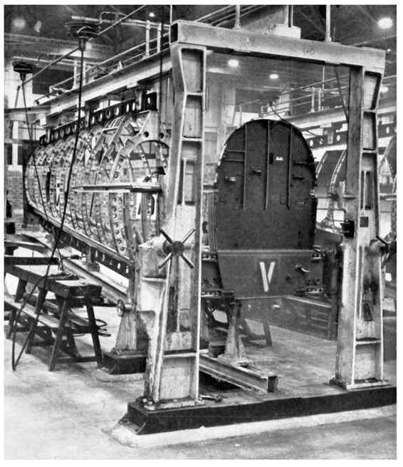
A line of assembly fixtures for the monocoque main section of the fuselage.
Mitchell’s design aims were to create a well-balanced, high-performance bomber interceptor and fighter aircraft capable of fully exploiting the power of the Merlin engine, while being relatively easy to fly.
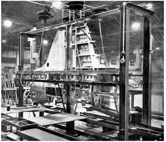
From the seventh frame, to which the pilot’s seat and (later) armour plating was attached, to the nineteenth, which was mounted at a slight forward angle just forward of the fin, the frames were oval, each reducing slightly in size and each with numerous holes drilled through them to lighten them as much as possible without weakening them.
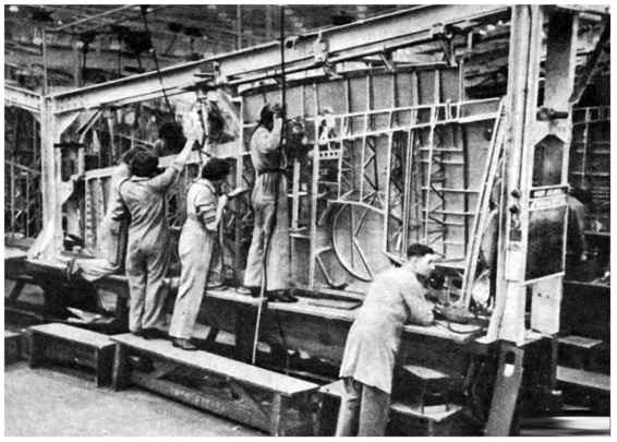
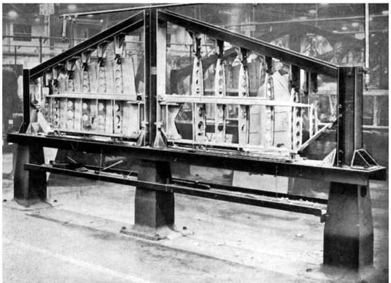
A close up of one of the main fuselage assembly fixtures in which the assembly and plating of the monocoque portion was completed.
A rear view of the main assembly fixture with the fuselage framework in position, along with two women workers.

The Spitfire’s airframe was complex: the streamlined, semi-monocoque duralumin fuselage featured a large number of compound curves built up from a skeleton of frames, starting from the main engine bulkhead to the tail unit attachment frame. Aft of the engine bulkhead were five half-frames to accommodate the fuel tanks and cockpit.

The jig in which the attachment holes in the stub spars were finish-reamed and the wing-root fillet attachment holes drilled.
Once the frames were skinned the fuselage was transferred to a series of jigs for a number of machining processes.
These jigs formed a guide for the tools used in a machining operation.
Paired-up assembly fixtures for rear fuselage units.
The U-shaped frame 20 was the last frame of the fuselage proper and the frame to which the tail unit was attached. Frames 21, 22 and 23 formed the fin; frame 22 incorporated the tailwheel opening and frame 23 was the rudder post. Before being attached to the main fuselage, the tail unit frames were held in a jig and the eight horizontal tail formers were riveted to them.
A combination of fourteen longitudinal stringers and two main longerons helped form a light but rigid structure to which sheets of alclad stressed skinning were attached. The fuselage plating was 24, 20 and 18 gauge thickness in order of thickness towards the tail, while the fin structure was completed using short longerons from frames 20 to 23, before being covered in 22 gauge plating.
Spitfire Mk IIA, P7666, EB-Z, ‘Observer Corps’, was built by Castle Bromwich, and delivered to 41 Squadron on 23 November 1940.


First stage showing the structural framework almost completed.
Mitchell has sometimes been accused of copying the wing shape of the Heinkel He 70, which first flew in 1932; but as Beverly Shenstone, the aerodynamicist on Mitchell’s team, explained ‘Our wing was much thinner and had quite a different section to that of the Heinkel. In any case it would have been simply asking for trouble to have copied a wing shape from an aircraft designed for an entirely different purpose.
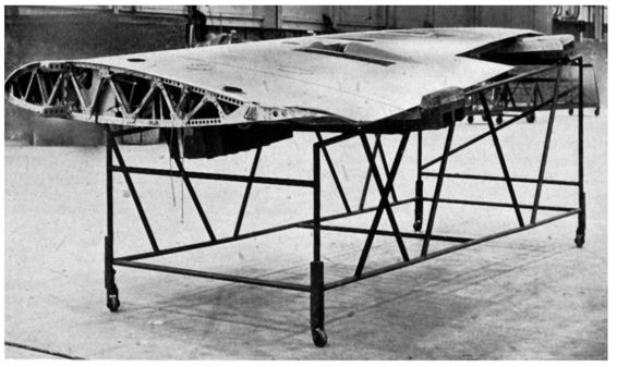
A port wing structure in the main assembly fixture. The skin plating has been applied to the upper surface. Final stages of wing assembly were performed out of the fixture with the wing held in a felt-lined cradle.
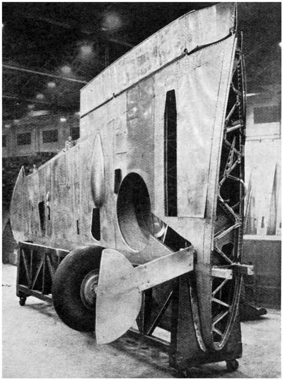
A completed wing - with an undercarriage leg and wheel - sits in a felt-lined cradle awaiting to be turned through ninety degrees and placed on a flat trolley (right) before being moved to the Spitfire final assembly line. The spar roots were mounted at the correct assembly height.
Lowering the Rolls-Royce Merlin engine on to its mounting in the early stages of intermediate assembly.
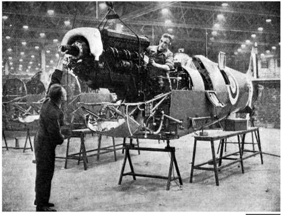

The tubular engine mounting for the Spitfire was assembled in the inverted position.
The skins of the fuselage, wings and tailplane were secured by rivets and in critical areas such as the wing forward of the main spar where an uninterrupted airflow was required, with flush rivets; the fuselage used standard dome-headed riveting. From February 1943 flush riveting was used on the fuselage, affecting all Spitfire variants.
Twin fixtures for the assembly of the tailplane surface.
The wings, supported in cradles on wheeled trolleys at the correct height in readiness for bolting up to the fuselage.
A feature of the wing which contributed greatly to its success was the innovative spar boom design, made up of five square tubes which fitted into each other. As the wing thinned out along its span the tubes were progressively cut away in a similar fashion to a leaf spring; two of these booms were linked together by an alloy web, creating a lightweight and very strong main spar.
The undercarriage legs were attached to pivot points built into the inner, rear section of the main spar and retracted outwards and slightly backwards into wells in the non-load-carrying wing structure. The resultant narrow undercarriage track was considered to be an acceptable compromise as this reduced the bending loads on the main spar during landing.
Ahead of the spar, the thick-skinned leading edge of the wing formed a strong and rigid D-shaped box, which took most of the wing loads. The radiators were housed in a new radiator-duct designed by Fredrick Meredith of the RAE at Farnborough; this used the cooling air to generate thrust, greatly reducing the net drag produced by the radiators. The leading-edge structure was later adapted to house integral fuel tanks of various sizes.
The British public first saw the Spitfire at the RAF Hendon air-display on Saturday 27 June 1936. Although full-scale production was supposed to begin immediately, there were numerous problems which could not be overcome for some time and the first production Spitfire, K9787, did not roll off the Woolston, Southampton assembly line until mid-1938.
All of the main flight controls on the Spitfire were originally metal structures with fabric covering. Designers and pilots thought that having ailerons which were too heavy to move at high speed would avoid possible aileron reversal, stopping pilots throwing the aircraft around and pulling the wings off. It was also felt that air combat would take place at relatively low speed and that high-speed manoeuvring would be physically impossible.
However, during the Battle of Britain, pilots found the ailerons of the Spitfire were far too heavy at high speeds, severely restricting lateral manoeuvres such as rolls and high speed turns, which were still a feature of air-to-air combat. Flight tests showed the fabric covering of the ailerons ‘ballooned’ at high speeds, adversely affecting the aerodynamics. Replacing the fabric covering with light alloy dramatically improved the ailerons at high speed.
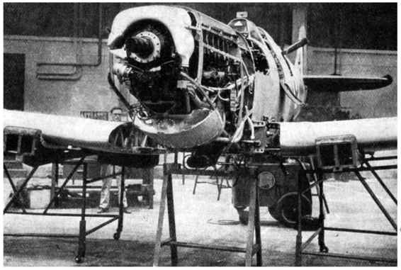
An undercarriage-actuation test being performed in the later stages of final assembly.


Original caption: Symbolic of Supermarine’s success in the construction of marine aircraft, Stranraers and Walruses form a fitting background for this convincing array of Spitfire single-seater fighters in production. Powered by a Rolls-Royce Merlin engine and peerless among standard fighters in performance and manoeuvrability, the Spitfire is by no means the ‘tricky’ production job which might be imagined. Construction is all-metal with a monocoque fuselage.
The first and most immediate problem was that the main Supermarine factory at Woolston was already working at full capacity fulfilling orders for Walrus and Stranraer flying boats. Although outside contractors were supposed to be involved in manufacturing many important Spitfire components, especially the wings, Vickers-Armstrong (the parent company) were reluctant to see the Spitfire being manufactured by outside concerns and were slow to release the necessary blueprints and subcomponents. As a result of the delays in getting the Spitfire into full production, the Air Ministry put forward a plan that production of the Spitfire be stopped after the initial order for 310, after which Supermarine would build Bristol Beaufighters. The managements of Supermarine and Vickers were able to persuade the Air Ministry that the problems could be overcome and further orders were placed for 200 Spitfires on 24 March 1938, the two orders covering the K, L and N prefix serial numbers.
In 1935, the Air Ministry approached Morris Motor Company to ask how quickly their Cowley plant could be turned to aircraft production. This informal enquiry regarding major manufacturing facilities was turned into a formal plan to boost British aircraft production capacity in 1936, as the Shadow factory plan, under the leadership of Herbert Austin. Austin was briefed to build nine new factories, and further supplement the existing British car manufacturing industry, by either adding to its overall capacity or capability to reorganise to produce aircraft and their engines.
Under the terms of the Shadow Plan, on 12 July 1938, the Air Ministry bought a site consisting of farm fields and a sewage works next to Castle Bromwich airfield in Birmingham. This shadow factory would supplement Supermarines original factories in Southampton in building the Spitfire. The Castle Bromwich Aircraft Factory ordered the most modern machine tools then available, which were being installed two months after work started on the site. Although Morris Motors under Lord Nuffield (an expert in mass motor-vehicle construction) at first managed and equipped the factory, it was funded by government money. When the project was first mooted it was estimated that the factory would be built for £2,000,000, however, by the beginning of 1939 this cost had doubled to over £4,000,000.
The Spitfire’s stressed-skin construction required precision engineering skills and techniques outside the experience of the local labour force, which took some time to train. However, even as the first Spitfires were being built in June 1940, the factory was still incomplete and there were numerous problems with the factory management, which ignored tooling and drawings provided by Supermarine in favour of tools and drawings of its own designs. With the workforce, while not completely stopping production, continually threatened strikes or ‘slow downs’ until their demands for higher than average pay rates were met.
Here Spitfires come together, as the original caption describes: ‘Lines of Spitfire fuselages in process of erection at a Government shadow factory. In contrast to that of its equally famous British counterpart, the Spitfire fuselage is of monocoque type with metal stressed skin covering. Plating operations are shown in progress on the centre line of fuselages, while a further row of camouflaged units may be seen on the right.
